10 Common Welding Defects: Causes, Inspection and Prevention
Porosity, cracks and fusion faults can weaken a weld. Learn what causes 10 common defects, how inspection finds them and which process checks help prevent them.
Weld quality depends on more than a clean-looking bead. A joint can contain hidden pores or incomplete fusion that weaken it, while visible issues such as undercuts and excess reinforcement can push its geometry outside the required limits. The practical starting point is to identify the defect, understand how it formed and check the finished weld against the acceptance criteria for its application.
Günter Doblinger, an expert on welding standards, draws a distinction between a discontinuity and a defect: a discontinuity is a deviation from the intended weld profile, but it becomes a defect only when it exceeds the permissible limits. Those limits depend on the standard and quality level that apply. For example, under EN ISO 5817 quality level B, a 0.2 mm undercut may be permitted on a 4 mm steel joint; at 0.3 mm, it exceeds the stated limit.
Ten defects to recognize
The common defects fall into several groups: gas or slag trapped in the weld, incomplete bonding or penetration, excess or insufficient weld metal, cracks, and spatter. Some are apparent at the surface; others require inspection methods that can examine the weld internally.
| Defect | What it looks like or means |
|---|---|
| Porosity | Gas voids at the surface or inside the weld. |
| Slag inclusions | Non-metallic residue trapped between weld layers or within the seam. |
| Lack of penetration or fusion | Weld metal has not fully bonded with the base material. |
| Cracks | Splits in the weld metal that can reduce joint capacity. |
| Undercuts | Grooves at the weld toe or between beads where melted base metal was not filled. |
| Excessive penetration and sagging | Too much weld metal passes through the root and bulges on the reverse side. |
| Crater cracks | Cracks form in the end crater as weld metal cools and shrinks. |
| Insufficient penetration | The root pass does not fuse through the joint as required. |
| Excess reinforcement | The weld bead rises beyond its required dimensions. |
| Welding spatter | Small metal particles leave the arc or weld pool and stick to the workpiece. |
Trapped gas and slag
1. Porosity
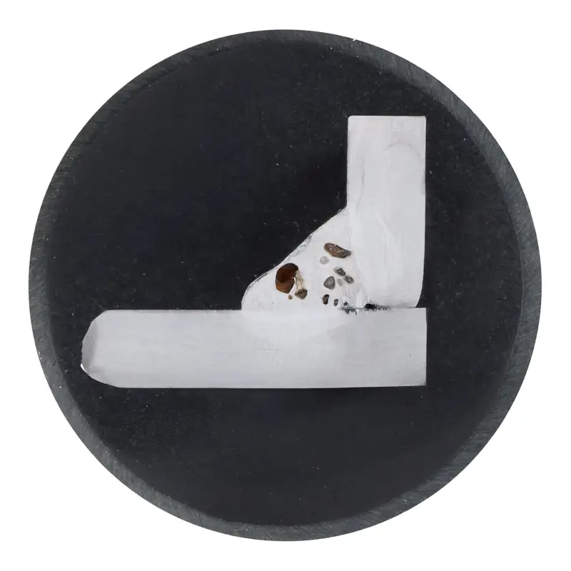
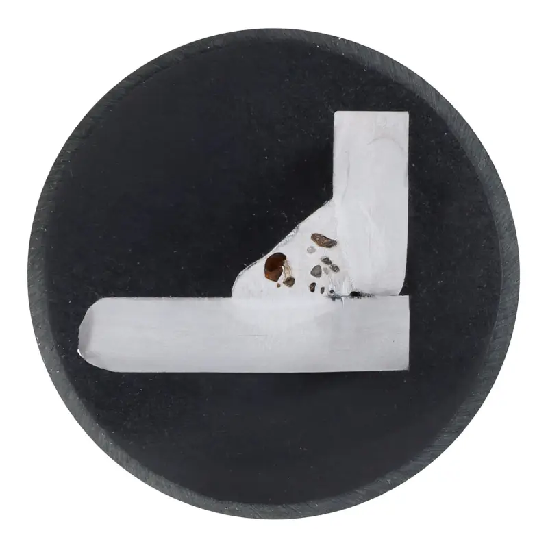
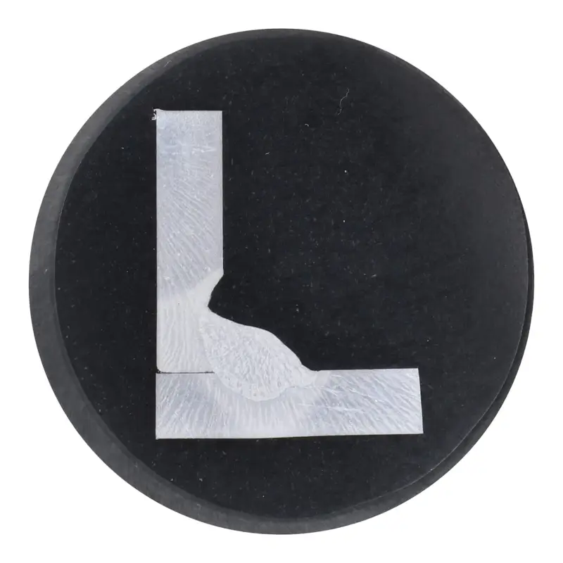
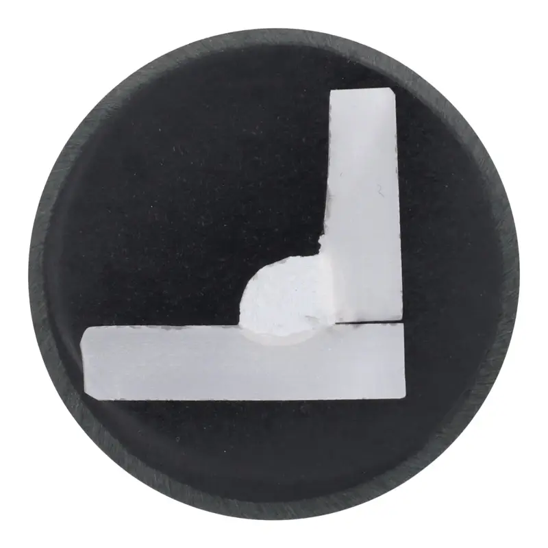
Porosity forms when gas is trapped in molten weld metal as it solidifies. Surface pores may be visible without magnification, but pores inside the seam can remain hidden until inspection. In a micrograph of a fillet weld, the gas voids appear as dark areas.
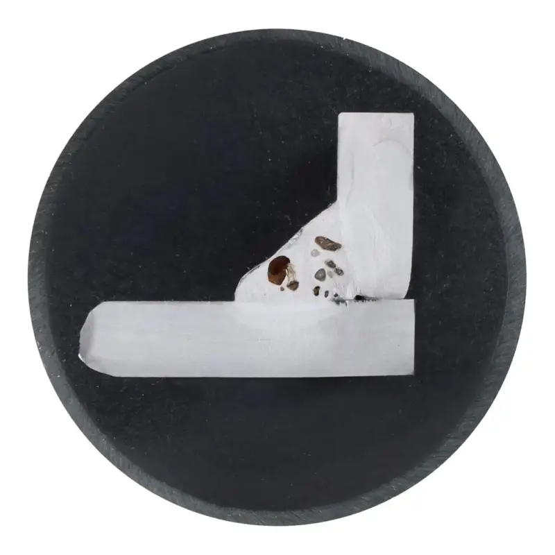
Gas voids appear as dark areas in this fillet weld micrograph.
Contamination is a frequent source: grease, oil, coatings, primer and residue from welding sprays can release gases into the weld pool. Shielding gas also matters. Too little allows air to reach the pool; too much can create turbulence that draws air in. A draft may disrupt the gas shield even when it is difficult to feel.
Doblinger’s main advice is to start with a clean surface: bare metal, free of oil, grease and coatings. Set shielding gas flow to suit the process and setup. The source gives a rule of thumb of wire diameter multiplied by 10, and stresses that both low and excessive flow can cause problems. Protect the weld area from drafts, including those near open doors on a worksite.
2. Slag inclusions
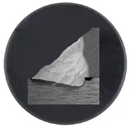
Slag inclusions are non-metallic residues embedded in the seam. They are most associated with processes that produce slag, including manual metal arc welding and flux-cored wire welding with MIG/MAG. In a macrosection, inclusions can appear as dark regions between weld layers. They disrupt the weld’s homogeneity and can reduce joint strength; cracks may develop later.
Slag left on a previous layer is a common cause. Surface scale, rust and other contamination can also become trapped. Additional contributors include low welding power, a long arc, poor joint preparation and torch handling that lets front slag move into the weld pool.
Remove slag thoroughly between passes and prepare the joint surfaces carefully. Keep the arc short and use sufficient welding power. With flux-cored wire, guide the torch so slag stays behind the weld pool. If a seam begins to look unusual, check joint preparation, settings and torch movement; small adjustments can address the cause.
Incomplete bonding and penetration
3. Lack of penetration or fusion
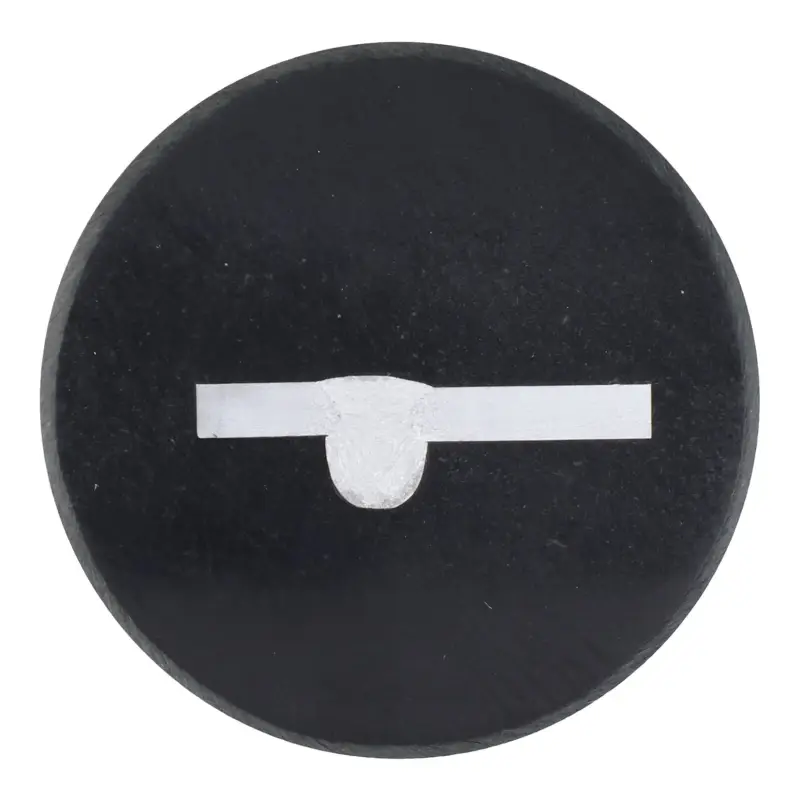
Lack of fusion means the weld metal has not bonded fully to the base material. The related term lack of penetration describes insufficient melting into the joint. Both can be difficult to see from the outside, yet they can significantly reduce a joint’s strength.
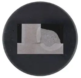
Common causes include unsuitable joint preparation, a root gap that is too small, insufficient power, excessive travel speed, a long arc and uneven torch guidance. The remedy is to treat preparation, parameters and technique as a connected set of variables. Match the joint geometry to the material and thickness, use adequate power, reduce travel speed when needed, shorten the arc and guide the torch evenly.
8. Insufficient penetration
Insufficient penetration in a butt weld specifically means the root pass has not fused through the root area. The joint may have a root face that is too high, a gap that is too narrow or an opening angle that is too small. Low welding power, high travel speed or an unfavourable torch position can compound the problem.
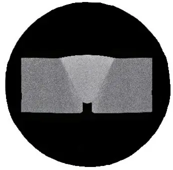
Check the prepared face height and root gap against the required joint dimensions. The source also recommends adequate stitch weld dimensions and selecting the required welding power. Because the defect may be internal, a sound-looking surface alone does not establish that the root is fused.
Cracks and edge geometry
4. Heat cracks
Heat cracks are linked to conditions as weld metal solidifies. A narrow, deep bead can raise the risk, while a very wide weld pool combined with a large gap can also contribute. The problem may involve several factors at once: internal stress in the component, unsuitable filler metal, restraint from the assembly, weld geometry and process settings.
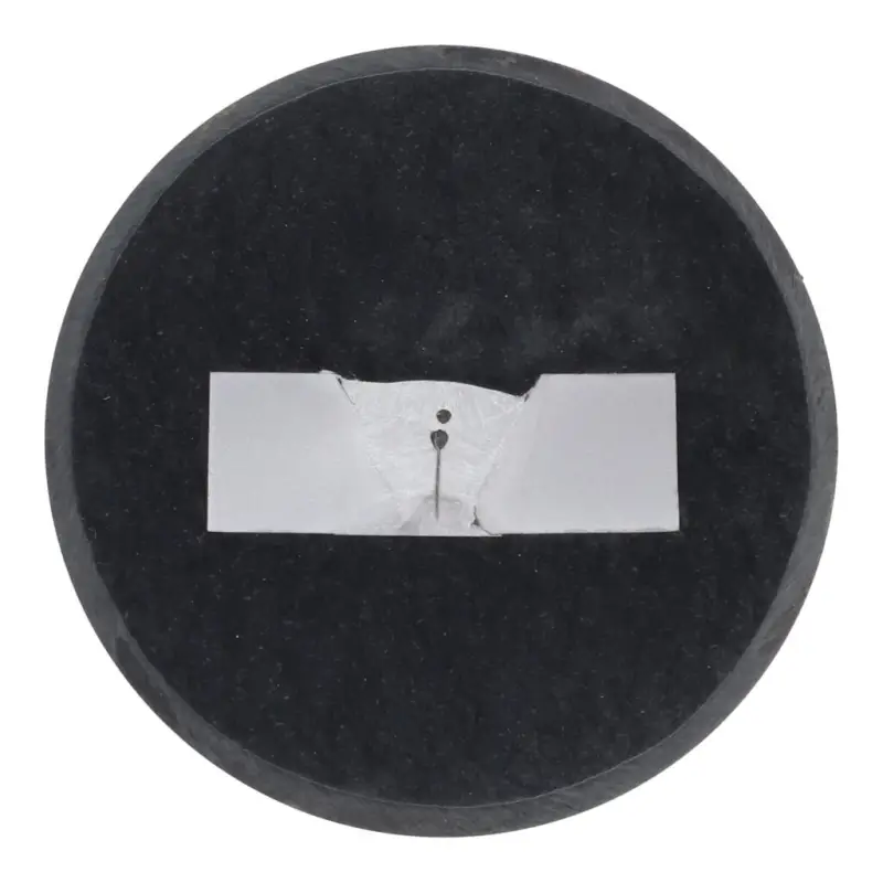
Prevention starts with coordinating the filler metal, workpiece preparation and welding parameters. Aim for a balanced bead width and depth, limit assembly stresses where possible, and account for welding sequence and restraint during planning. Doblinger cautions that cracking often reflects a combination of unfavourable conditions rather than a single mistake.
5. Undercuts
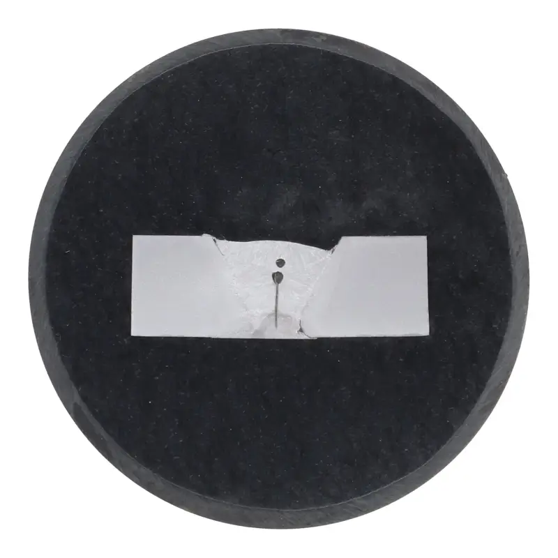
An undercut is a groove where the base metal has melted but the deposited weld metal has not filled the area. It can occur at the seam edge in fillet and butt welds, creating a notch that can affect strength and durability. A macrosection shows the characteristic depression at the weld toe.
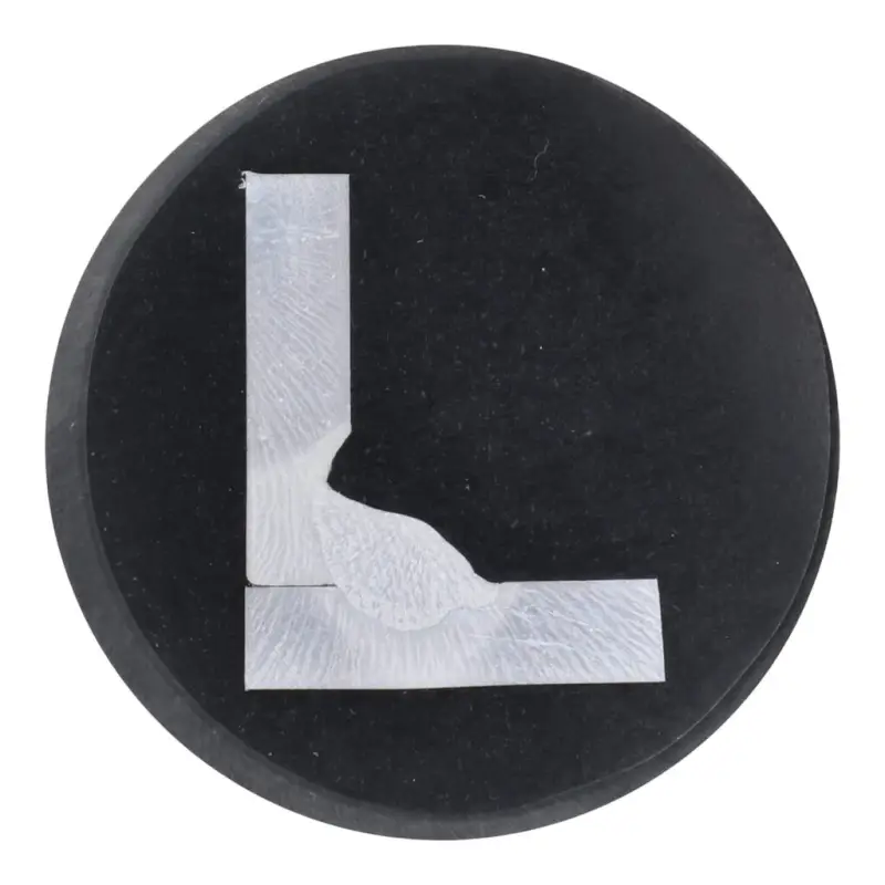
Moving too quickly may leave insufficient metal at the sides. Inadequate side-to-side torch movement can also melt base metal without replacing enough of it. A long arc, high voltage and a poor torch angle add to the risk.
Match travel speed, power and torch guidance to the joint geometry. Doblinger recommends reducing speed and using adequate weaving width where appropriate. Shorten the arc, check torch angle and inspect the weld edges as work progresses. The source gives approximate positioning guidance: hold the torch at about 45° for fillet welds where possible, and as vertically as possible for butt welds to deposit metal on both sides.

6. Excessive penetration and sagging
When too much weld metal passes through the root, it creates a bulge on the reverse side, often called sagging. This occurs mainly in butt welds and can result from excessive heat input, a gap that is too wide or a poor balance between power and travel speed.
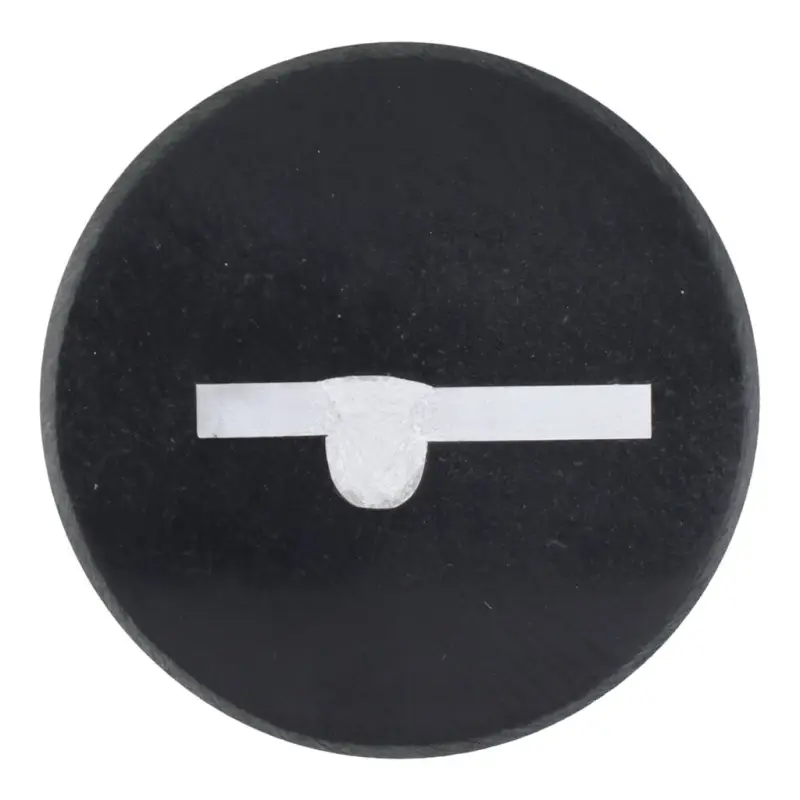
Control heat input for the material and component thickness, and prepare the joint accurately. Keep the gap within its specified tolerance, make sure the root pass is appropriately sized, and balance amperage with travel speed. A pronounced root bulge is a reason to recheck both the gap and the applied power.
7. Crater cracks
The end of a weld needs deliberate control. As weld metal cools, it contracts; if the end crater is left short of metal, that shrinkage can produce fine cracks. Abruptly cutting power, pulling the torch away too quickly or losing shielding gas before the pool solidifies can all contribute.
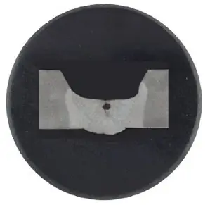
Fill the crater as fully as possible and end the process in a controlled way. Reduce power gradually where the equipment and process allow, keep the torch in position briefly after switching off, and maintain shielding gas until the pool solidifies. The final centimetre deserves the same attention as the rest of the seam.
Excess weld metal and spatter
9. Excess reinforcement
Excess reinforcement occurs when the bead extends beyond its required dimensions. Too much deposited metal can alter component geometry and may require rework. A slow travel speed, excessive filler feed, incorrect torch position or an imbalance between process parameters can cause the bead to build up instead of spreading evenly.
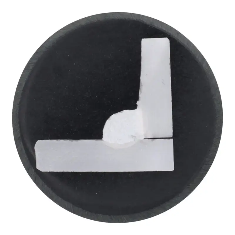
Review travel speed, wire speed, welding power and torch guidance together. Increasing travel speed or reducing filler metal may help, provided the resulting weld still meets the required dimensions and fusion criteria. Doblinger notes that modest parameter changes can improve the profile.
10. Welding spatter
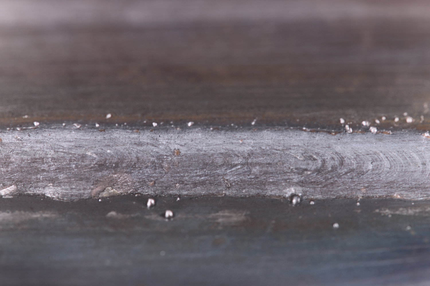
Spatter consists of metal particles ejected from the arc or pool that adhere to the workpiece. Dirty surfaces, unsuitable parameters, poor filler metal quality and an unfavourable combination of voltage, amperage and wire speed can all contribute.
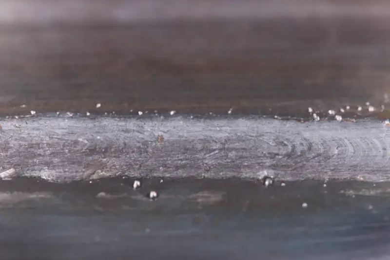
Use clean workpiece surfaces and suitable filler metal, then tune the settings for the base material, filler and welding task. Spatter has several possible causes, so the useful check is to assess the parameter combination rather than assume one adjustment will address every case.
Inspection and process control
Visual testing can reveal external issues such as undercuts, surface pores and spatter. Internal flaws call for non-destructive testing selected for the material and type of imperfection. The methods listed include visual testing (VT), penetrant testing (PT) for surface-breaking defects, magnetic particle testing (MT) for magnetizable materials, X-ray inspection (RT) for internal defects and ultrasonic testing (UT) for internal imperfections.
Porosity illustrates why inspection choice matters: pores may be visible at the surface, while internal pores can require X-ray inspection. The applicable acceptance criteria also matter. EN ISO 5817 is cited for steel and EN ISO 10042 for aluminum; AWS D1.1 and AWS D1.2 provide US acceptance criteria for steel and aluminum respectively, while AWS A3.0 defines the distinction between discontinuity and defect. Which limit applies depends on the job’s requirements.
Modern welding systems can support process consistency through stable arc processes, welding programs, repeatable parameters and digital assistance features. Manual, robotic and automated systems can help standardize work, but the machine is only one part of the setup. Torch guidance, consumable condition, shielding gas supply and workpiece preparation all affect the result.
For practitioners, prevention begins before striking the arc: prepare the joint and surfaces, verify the setup, then watch how the bead forms and terminates. When a defect appears, tracing it to its process cause is more useful than treating the visible symptom alone. That discipline helps protect joint quality and limit rework.
 Choosing Single, Double, Welded Flap and Repair Keder for Fabrication
 Houston Engineering Team Builds a Welcoming Golf Tournament at East River 9
 MIG Transfer Modes: Choosing Between Short Circuit, Spray and Pulse