Impulse vs Reaction Turbines: Energy Transfer, Flow and Installation
Impulse turbines extract energy from a free jet; reaction turbines use pressure and velocity changes inside a full, enclosed runner.

The key distinction between impulse and reaction turbines is where the water transfers energy to the runner. In an impulse machine, a nozzle converts the available hydraulic energy into a high velocity jet before the water reaches the runner. In a reaction machine, water enters the runner with pressure energy still available, and both pressure and velocity change as it flows through the blade passages. That difference shapes the turbines’ flow paths, enclosures, controls and typical installation arrangements.
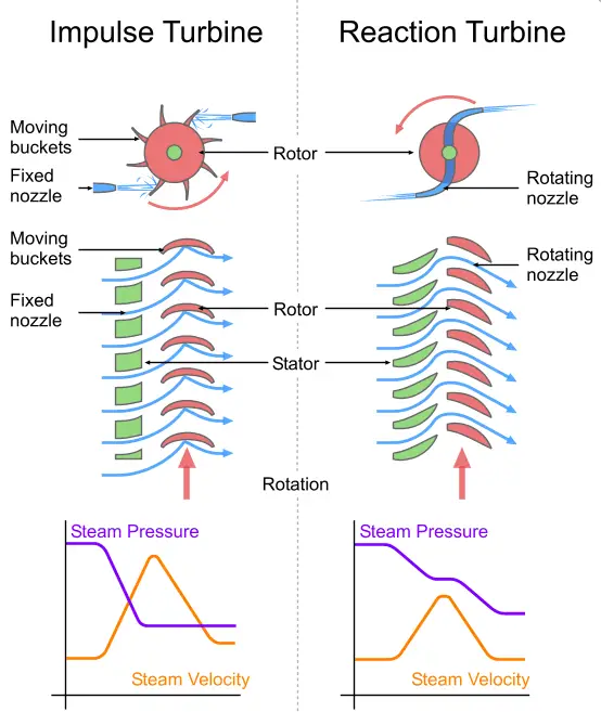 |
| Schematic comparison of an impulse turbine and a reaction turbine. The stator is stationary; the runner is the rotating part of the machine. Image source: Emoscopes (Wikimedia Commons) |
Where the pressure change occurs
An impulse turbine’s nozzle accelerates the water into a jet aimed at the runner buckets. The pressure remains approximately atmospheric as the jet passes across the runner, while its direction and velocity change. The runner extracts energy from the change in the water’s momentum. A Pelton wheel is an example of this arrangement.
A reaction turbine uses a different path. Water enters the runner passages under pressure, and pressure falls as it passes through the blades. The water also changes velocity and direction, transferring energy to the rotating runner along the way. The passages are filled with water during operation, so the runner works within a continuous flow rather than being struck by separate free jets.
This distinction is captured by the degree of reaction: it is zero for an impulse turbine and greater than zero, up to and including one, for a reaction turbine. The value describes the share of the energy transfer associated with pressure change in the runner. It helps distinguish the operating principle, though it does not by itself establish which turbine is more efficient for a particular installation.
Flow path and machine enclosure
Impulse turbines admit water as one or more jets. The jets strike the runner buckets, and air has free access around them. The casing therefore does not need to contain pressurized water or perform the same hydraulic role as a reaction turbine casing. It still helps limit splashing and direct discharged water toward the tail race.
Reaction turbines admit water around the runner’s circumference. Their runner passages must remain filled, which requires a watertight enclosure around the runner. A scroll casing and stay ring can direct and support the incoming flow; guide vanes regulate how water enters the runner. Francis, Kaplan, propeller, Deriaz and tubular turbines are examples of reaction designs.
The flow direction also differs across common designs. Water reaches an impulse wheel tangentially as a jet. Reaction turbines can use radial and axial flow through the runner, with the exact path depending on the turbine type. That geometry affects how the machine receives water and connects to the downstream passage.
Installation and flow control
Impulse turbines are installed above the tail race and do not use a draft tube. A needle valve in the nozzle controls the jet flow. The jet and runner operate with air around the buckets, so the turbine does not need to remain submerged in a water-filled passage.
Reaction turbines commonly connect to the tail race through a draft tube, a passage that gradually expands downstream of the runner. The tube guides water out and forms part of the machine’s flow path. Depending on the arrangement, a reaction turbine can sit above or below the tail race. Guide vanes regulate its incoming flow, alongside components such as the scroll casing and stay ring.
Matching the turbine to the site
The comparison associates impulse turbines with high water heads and lower discharge, and reaction turbines with low or medium heads and medium or high discharge. These are broad selection cues, not a substitute for evaluating the actual site and operating range. The available head and flow, the required machine arrangement, and the chosen turbine geometry all matter to a design decision.
The source comparison describes impulse turbines as having greater hydraulic efficiency and requiring less maintenance. Those claims should be read as general comparisons rather than fixed outcomes: efficiency and maintenance depend on the specific machine and its operating conditions. The more dependable distinction for an initial assessment is the energy-transfer mechanism. A nozzle-driven jet and an open runner point toward an impulse design; pressure change within a full, enclosed runner points toward a reaction design.
For engineers comparing options, that mechanism is the practical starting point. It links the site’s head and discharge to the required casing, flow-control hardware and discharge arrangement—and makes clear which design details need closer evaluation.
 Choosing Single, Double, Welded Flap and Repair Keder for Fabrication
 Houston Engineering Team Builds a Welcoming Golf Tournament at East River 9
 MIG Transfer Modes: Choosing Between Short Circuit, Spray and Pulse