Smartphone Flashlight Morse Link Uses BPW34 Photodiode and LM393
A low-cost optical link sends Morse text from a phone flashlight to a BPW34 receiver, with an LM393 and Python handling detection and decoding.
A phone flashlight, a photodiode and a few lines of Python are enough to demonstrate a visible-light data link. This roughly ₹400 proof of concept sends text as timed Morse-code flashes and receives it without a microcontroller. Its value is in showing the full signal path: phone hardware limits the rate, an analogue threshold circuit cleans up the optical signal, and software reconstructs characters from pulse timing.

From phone light to terminal text
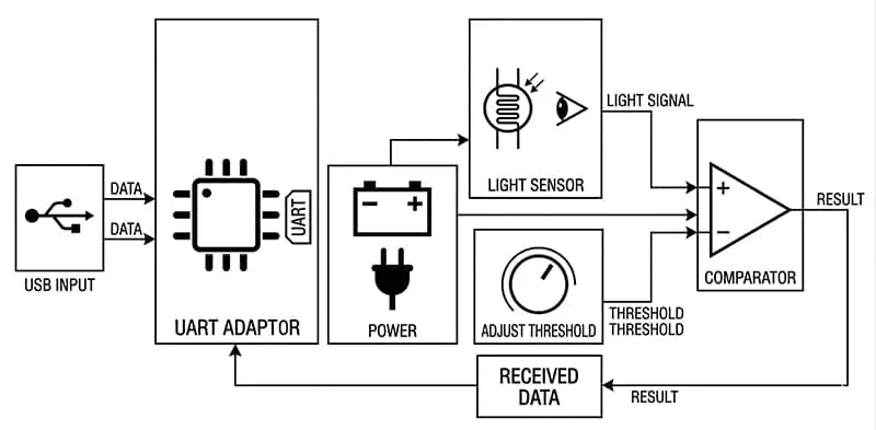
The transmitter is a smartphone app that converts letters and numbers into Morse code, then switches the flashlight on and off for each symbol. The receiver uses a BPW34 photodiode to turn changing light intensity into an electrical signal. An LM393 comparator compares that signal against an adjustable threshold and produces digital pulses that a computer can read.

The comparator output connects to the CTS pin of a USB-to-TTL adapter. That adapter provides the bridge to a Python program running on the computer; the project does not put a microcontroller between the sensor and the decoder. The script measures pulse durations and the gaps between them, identifies dots and dashes, and prints decoded characters in the terminal as they arrive.


This arrangement makes the division of work clear. The photodiode senses the optical carrier, the comparator turns a small analogue variation into logic-level transitions, and the program interprets those transitions as symbols. Each stage can be examined independently, which makes the setup useful for learning about optical sensing as well as serial input and timing analysis.

Morse timing carries the framing
The link uses on-off keying (OOK): light on represents a transmitted mark, while light off represents a gap. Morse supplies the symbol encoding, and the duration of each mark distinguishes a dot from a dash. A dot is about 30ms; a dash lasts three times as long. Gaps also have defined timing between elements, letters and words, allowing the receiver to infer boundaries without separate framing bits or a more elaborate communication protocol.
That simplicity shifts the work into accurate timing. The Python decoder must distinguish a long flash from a short one and use the intervening dark periods to decide whether it has reached the next Morse element, a new letter or a word boundary. If the timing varies too much, the receiver can assign the wrong symbol or split a character incorrectly. The comparator threshold matters too: it must separate the received flashes from background illumination well enough to create clean transitions.

The LM393’s adjustable threshold gives the receiver a way to set that decision point for the optical signal it sees. The circuit is therefore doing more than amplifying a sensor output: it converts an analogue light response into a digital pulse train that software can time. Ambient light is part of the operating environment, so the threshold setting and the optical conditions affect how reliably the computer sees each transition.
Phone hardware sets the pace
The reported reliable operating point is about 30ms per interval or slower, corresponding to roughly 30–40 bps. The limiting factor is the phone flashlight, not a stated processing limit in the Python decoder. A white LED typically produces white light by combining blue emission with a yellow phosphor layer, and that phosphor responds more slowly than the LED’s underlying electrical switching. Operating-system latency adds further delay when the phone controls the flashlight.
Those effects make the transmitted light less suitable for very short, sharply timed pulses. Slowing the symbol interval gives the receiver more time to distinguish the intended marks and gaps. The result is a modest data rate, but one that fits the project’s purpose: a visible demonstration of how information can ride on light, rather than a high-speed replacement for a radio link.
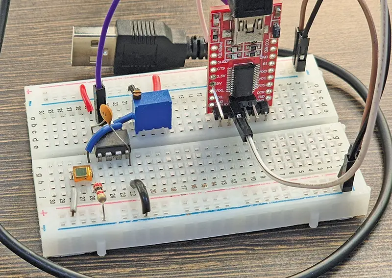
The prototype is built on a breadboard, keeping the photodiode and comparator circuit accessible for inspection. The reported build is rated medium in complexity and takes about five hours. Those estimates describe the project as presented; the available details do not specify a transmission distance, a component-by-component cost breakdown or measured performance under different lighting conditions.
What the demonstration teaches
The project connects several practical ideas that are often taught separately: optical transmission, photodiode sensing, comparator thresholding, pulse-width measurement and software decoding. It also shows how a USB-to-TTL adapter’s serial control line can expose a digital signal to a computer program, even when the project does not use a conventional microcontroller serial stream.
As a learning build, the most useful result is the boundary between a working demonstration and a dependable data link. Morse makes the encoding easy to see, while the phone’s flash timing and the receiver’s threshold make the physical limitations visible. The roughly 30–40 bps rate is a reminder that the transmitter’s real response, rather than the nominal speed of its control command, determines how quickly this optical link can operate.
 Choosing Single, Double, Welded Flap and Repair Keder for Fabrication
 Houston Engineering Team Builds a Welcoming Golf Tournament at East River 9
 MIG Transfer Modes: Choosing Between Short Circuit, Spray and Pulse