Infineon PSOC Edge E84 Baby Monitor Prototype Combines Camera, Radar and Cry Detection
The prototype integrates live video, 60GHz radar, on-device cry classification and rule-based audio playback on one embedded platform.===
A monitor prototype with a clear engineering boundary
The interesting part of this baby-monitor project is the way it brings several sensing and feedback paths onto one embedded platform. An Infineon PSOC Edge E84 evaluation kit combines a live camera view, 60GHz radar motion sensing, audio playback and on-device cry classification. The system also uses simple rules to decide when to play a song. That makes it a useful integration exercise; it does not make it a device for judging an infant’s condition.

Image Source: AkuAku/stock.adobe.com; generated with AI
Safety note: This is an engineering demonstration built on an evaluation platform, not a medical device. Its outputs have not been clinically validated and must not be used to determine whether an infant is breathing, present or safe. Caregiver supervision and established safe-sleep practices still apply.
Market estimates help explain the interest in connected monitors: the smart baby monitor market was valued at US$1.35 billion in 2022 and is projected to reach about US$2.48 billion by 2030.[1] But monitoring features sit alongside, rather than replace, safe-sleep guidance. The American Academy of Pediatrics recommends placing infants on their backs on a flat, non-inclined surface, keeping the sleep space uncluttered, and having the infant sleep in the parents’ room on a separate infant sleep surface for at least the first six months.[2]
Local processing is the project’s other defining choice. The global edge AI market was estimated at approximately US$24.91 billion in 2025 and is forecast to reach US$118.69 billion by 2033, with low-latency processing, IoT growth and interest in privacy-focused local intelligence cited as drivers.[3] Those figures describe a broad market trend; they don’t establish how well this prototype performs. The engineering question here is narrower: can video, radar, audio classification and user feedback run together on an embedded system without relying on a cloud service or external computer?
What the prototype combines
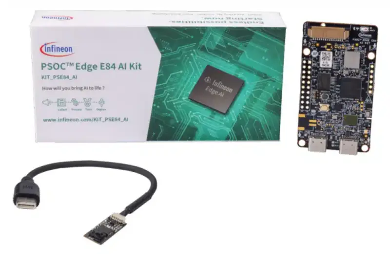
The guide builds the system on the Infineon PSOC Edge E84 AI Evaluation Kit (KIT_PSE84_AI), starting from Infineon’s open-source PSOC_Edge_Graphics_LVGL_Demo. It adds a 4.3-inch MIPI DSI display, a USB camera feed, TDM audio playback through a TLV320DAC3100 codec and speaker, XENSIV™ BGT60TRxx 60GHz radar motion detection, and a LiteRT for Microcontrollers cry-classification model running on an Arm® Ethos™-U55 neural processing unit (NPU).
A rule-based controller links the inputs to audio playback: it starts a song after three detected cries within five minutes, or after eight seconds of sustained radar agitation. That’s a deliberately simple trigger scheme. The guide’s emphasis is on the wiring, firmware setup, subsystem integration and debugging needed to make the demonstration work reliably, including symptoms, root causes and code or configuration fixes.
The project’s advertised source material includes a  banner and an
 banner.

Parts, code and development tools
The hardware list centers on the Infineon KIT_PSE84_AI PSOC™ Edge E84 AI evaluation kit. It also calls for an 800×480 IPS 4.3-inch MIPI DSI capacitive-touch display with a 15-pin DSI ribbon and four-pin power/I²C cables; a 4Ω, 3W passive speaker with bare leads; and a Molex PicoBlade connector assembly. The specified connector parts are a 1.25mm, two-position, right-angle SMT header (Mouser #538-53261-0271) and a two-position crimp housing (Mouser #538-51021-0200). Add a 15-pin, 0.5mm-pitch FFC, soldering iron and solder, crimp tool, Windows 11 development PC, and a USB Type-C cable for programming, UART debug and power rated for at least 5V/500mA.
The software references are the project GitHub repository, Infineon ModusToolbox 3.x with GCC Arm toolchain and Device Configurator, and Infineon’s PSOC_Edge_Graphics_LVGL_Demo base project. The recorded development versions are ModusToolbox tools 3.7, Device Configurator 5.60 and GCC 14.2.1. The remaining dependencies are the TLV320DAC3100 audio codec driver, emUSB-Host middleware and USB video class driver, the DEEPCRAFT™ baby-cry model library (babycry_lib_eval.a), Python 3.x, FFmpeg, and Tera Term or a similar terminal emulator.
Processing architecture and build sequence
The PSOC Edge E84 integrates three processors: a Cortex®-M33 for security and system management, a Cortex-M55 for the application, and an Ethos-U55 NPU for neural-network inference. The kit also provides 64MB of flash, a display controller and 2D GPU, digital microphones, an audio codec, 60GHz radar and a USB host port. Firmware is organized as a three-project ModusToolbox workspace—proj_cm33_s, proj_cm33_ns and proj_cm55—with the guide’s application running on the CM55 under FreeRTOS.
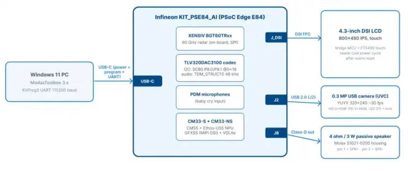
The work proceeds through physical assembly, memory reallocation and firmware configuration. First, solder the J8 speaker connector, connect the display and attach the USB camera. Then enlarge the CM55 flash partition from 2.75MB to 6MB, configure the 4.3-inch panel and add the codec, radar, machine-learning and emUSB-Host libraries. Python and FFmpeg convert MP3 assets into 48kHz PCM. The guide then builds, programs and checks the display/UI, camera, audio, cry detector and radar in sequence before enabling the song auto-play state machine and working through documented faults.
That flash change is a hard prerequisite: the build needs about 5.4MB, much of it for raw audio. A 30-second song alone occupies 2.88MB as PCM. The stock CM55 allocation is only 2.75MB, while roughly 55MB of flash remains unused just beyond that partition, so the allocation can be extended in Device Configurator. It’s a configuration limit, not a physical capacity limit.
The board is a ready-to-use platform for exploring edge-AI applications, with a camera, microphones, motion and environmental sensors, 60GHz radar, Wi-Fi and Bluetooth® connectivity. It ships with demonstration firmware and connects to a PC over USB Type-C, so developers can start from an existing platform. The specific build uses the kit’s display, camera, radar and audio paths.
How the peripherals fit together
The display is an 800×480 touch panel with a bridge microcontroller that turns the MIPI DSI stream into panel signals. A 15-pin FFC connects it to J_DSI, and the board support package includes drivers under the W4P3INCH_DISP build target.

The 0.3MP USB camera is a standard USB Video Class webcam. It sends uncompressed YUYV frames at 320×240 and about 30fps through the dual-role USB Type-C port J2. Connecting it switches the port into host mode, powers the camera and lights D11; firmware enumerates the camera, so no pin mapping, soldering or I²C setup is needed.
The XENSIV BGT60TRxx radar is already soldered to the board and communicates over SPI. It detects motion in darkness and supplies presence and breathing indicators to the GUI’s SAFETY tab. In this project, it adds a motion signal that can register restlessness before crying begins.
Audio output runs through the board-mounted Texas Instruments TLV320DAC3100. I²C on SCB0 at address 0x18 controls the codec; TDM carries 48kHz samples to the speaker. The J8 speaker footprint is unpopulated, so it needs a connector soldered on before the speaker can be used.
Firmware layers and data flow
ModusToolbox and the Peripheral Driver Library provide the build and device configuration environment. Device Configurator sets pins, clocks and memory layout, then generates C files and linker scripts. FreeRTOS gives graphics, camera, radar, cry detection and watchdog functions their own tasks, keeping one subsystem from blocking the others.
LVGL v9 draws the interface into two frame buffers in the device’s internal SoCMEM: while the panel displays one frame, the software prepares the next. For camera capture, emUSB-Host supplies the USBH_VIDEO API. The camera task creates USBH_Task and USBH_ISRTask on the CM55; once attached, the application matches vendor and product IDs, selects uncompressed 320×240 video and opens a stream. A callback delivers video packet by packet. The BSP already configures the USB block, so Device Configurator needs no USB changes.
Cry classification uses Infineon’s pre-trained DEEPCRAFT™ model, distributed as the compiled babycry_lib_eval.a library and run through LiteRT for Microcontrollers on the Ethos-U55. The NPU needs a scratch area called the tensor arena; both that arena and the model must reside in SoCMEM. Song and startup-chime files begin as MP3, but decoding them on the microcontroller can cause crashes. Instead, regen_audio_48k.py invokes FFmpeg on a PC to produce uncompressed PCM samples.
Assembly starts with the speaker connection
Before powering the system, solder the Molex PicoBlade 1.25mm right-angle header onto the two-pad J8 surface-mount footprint near the codec. Crimp the speaker wires into the matching housing and plug it into the header. If the connector is absent, the speaker simply won’t work; the firmware gives no error.

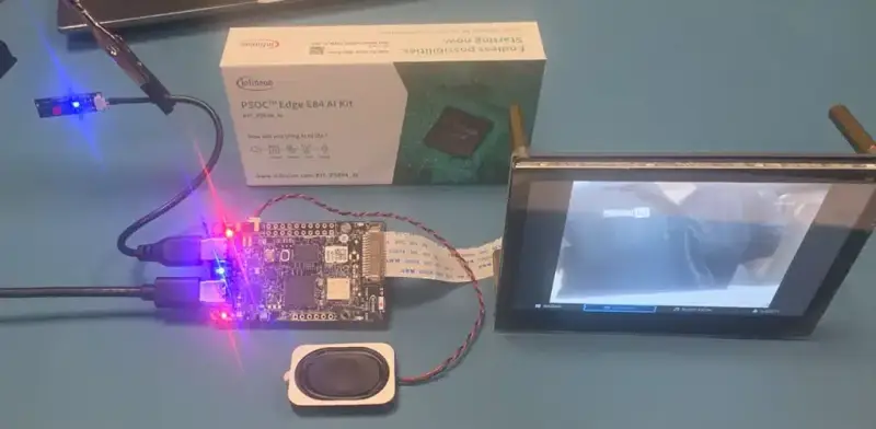
For the display, open the zero-insertion-force latch at J_DSI, insert the 15-pin FFC with its metal contacts facing the board, then close the latch. Connect the other end to the panel’s DSI input, with the stiffener strip facing away from the contacts. Attach the 0.3MP camera to J2 with the supplied cable and check that D11 lights, indicating host mode and camera power. Finally, connect the board to the PC over USB Type-C. KitProg3 appears as a COM port for programming and 115200-baud debug output; confirm that the power LED is on.
Expanding CM55 Memory
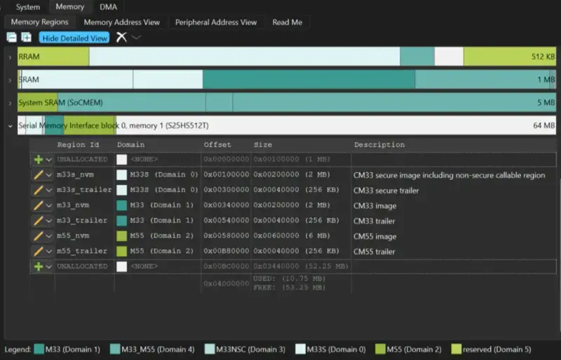
The CM55 firmware needs more nonvolatile memory for this build, and the partition boundary has to move with it. In the Device Configurator’s **Memory** tab, increase `m55_nvm` from `0x2C0000` (2.75 MB) to `0x600000` (6 MB). Leave the CM33 partitions alone: they precede CM55 in the address map. Then set `m55_trailer`’s offset to `0x00B80000`, the new end of `m55_nvm` (`0x00580000 + 0x00600000`). Its size stays `0x00040000`. Check the offset manually even if the configurator appears to update it; leaving it at `0x00840000` makes the trailer overlap the expanded region and triggers a configurator error. Save and generate the configuration to rewrite `cymem_gnu_CM55_0.ld` and the related headers. Rebuild all three projects and reflash. The CM33 code uses CM55’s start address, `0x60580000`, rather than its size, so that reference doesn’t need to change.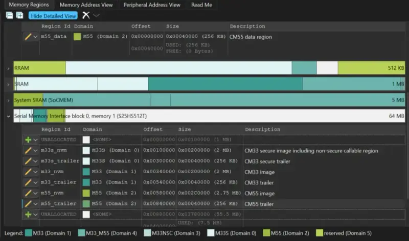
Configuring the Firmware
Base project and display target
Start with version 2.3.0 of Infineon’s PSOC_Edge_Graphics_LVGL_Demo, tagged `release-v2.3.0` on GitHub as `mtb-example-psoc-edge-gfx-lvgl-demo`, and open it in ModusToolbox. It creates three projects. The version matters: 2.6.x uses LVGL v9.5.0 and a different directory layout, so these instructions don’t transfer unchanged. Set the 4.3-inch panel in the application-root `common.mk`: ```make CONFIG_DISPLAY = W4P3INCH_DISP ``` `proj_cm55/Makefile` reads that setting and selects the `MTB_DISPLAY_W4P3INCH_RPI` display driver and `MTB_CTP_FT5406` touch driver. Run `make getlibs` from each project directory to fetch its middleware. The I²C setup has a trap. Enable SCB0 as a 1.8 V, 400 kHz master on P8.0 (SCL) and P8.1 (SDA). Select 16-bit divider 0, `CYBSP_I2C_CONTROLLER_CLK_DIV`, which SCB5 also uses for the display. Keep the divider value at 32: changing it also changes the display’s I²C speed. Instead, turn on Manual data rate control and set the low phase duty cycle to 5 and the high phase to 3, producing about 390 kHz. Generate the configuration after confirming the Notices pane has no errors.Adding codec, radar, ML, and USB camera support
Append these entries to `proj_cm55/Makefile`: ```make # audio codec + radar driver sources SOURCES += ../mtb_shared/release-v2.0.0/xensiv_bgt60trxx.c \ ../mtb_shared/release-v2.0.0/xensiv_bgt60trxx_mtb.c \ ../mtb_shared/release-v2.0.0/xensiv_bgt60trxx_edge.c \ ../audio-codec-tlv320dac3100/mtb_tlv320dac3100.c INCLUDES += ../audio-codec-tlv320dac3100 # DEEPCRAFT babycry model on the Ethos-U55 COMPONENTS += ML_TFLM ML_FLOAT32 ML_INT8x8 CMSIS_DSP U55 DEFINES += CY_ML_MODEL_MEM=.cy_socmem_data CY_ML_ARENA_MEM=.cy_socmem_data LDLIBS += ./ready_models/CONFIG_$(CONFIG)/TOOLCHAIN_$(TOOLCHAIN)/babycry_lib_eval.a # USB camera: emUSB-Host video class (kit rev *A) COMPONENTS += USBH USBH_BASE CY_IGNORE += ./driver/camera/mtb_dvp_camera_ov7675.c ``` The model and tensor arena definitions place both in SoCMEM. That placement is required because the NPU can’t access external PSRAM. For the revision *A USB camera, create `proj_cm55/deps/emusb-host.mtb` with this line, then run `make getlibs` again: ```text mtb://emusb-host#release-v2.2.0#$$ASSET_REPO$$/emusb-host/release-v2.2.0 ``` ### Generating the audio PCM assets The repository already contains `proj_cm55/lullaby_data.c` and `proj_cm55/welcome_sound_data.c`. Regenerate them only if you want to use different MP3 files. Put `regen_audio_48k.py`, your song MP3, and your welcome-sound MP3 from the repository root into the project root—the directory containing `proj_cm55`. Install FFmpeg, make sure it’s on `PATH`, check the filenames, and run: ```text python regen_audio_48k.py ``` The script converts the song to 48 kHz mono PCM, trims it to 30 seconds (1,440,000 samples, about 2.88 MB), and writes `proj_cm55/lullaby_data.c`. It converts the welcome sound to the same format with loudness normalization; that file is 3.71 seconds long and becomes `welcome_sound_data.c`.Project files and build
The feature work lives in `proj_cm55`. The `proj_cm33_s` and `proj_cm33_ns` projects remain unmodified. Across the project, 24 files were created or changed, with a Python helper at the repository root: 13 new subsystem modules, five edits to base-demo files, one patch to third-party `minimp3.h`, and four earlier-generation files retained under `superseded_not_in_build` for reference. Those retained files aren’t built. Table 1 identifies each file’s role.Table 1. Files created or modified for this project, grouped by role
| File | Status | Purpose |
|---|---|---|
| camera_sensor.c/.h | New | USB (UVC) camera capture task; converts YUYV frames to RGB565 in SoCMEM for the GPU (kit rev *A). |
| radar_sensor.c/.h | New | BGT60TR13C signal processing: range-gated magnitude, motion, presence, and the breathing bandpass filter. |
| radar_ui.c/.h | New | LVGL touch dashboard: the RADAR, CAMERA, BABY MON, and SAFETY tabs, including the SAFETY privacy gate. |
| cry_detector.c/.h | New | Captures pulse-density modulation (PDM) microphone audio and runs the DEEPCRAFT babycry model via LiteRT for Microcontrollers on the Ethos-U55 NPU. |
| lullaby_player.c/.h | New | Multi-sensor song state machine (cry-count and motion triggers, calm-based auto-stop) and playback control. |
| buzzer.c/.h | New | Interrupt-driven TDM/I²S audio driver; always-on bit clock, tone mode, and PCM playback mode. |
| boot_screen.c/.h | New | Full-screen Mouser boot overlay and the timer that synchronizes it with the welcome chime. |
| lullaby_data.c/.h | New (generated) | 48kHz PCM sample array for the song, produced by regen_audio_48k.py. Required for the build to link. |
| welcome_sound_data.c/.h | New (generated) | 48kHz PCM sample array for the boot chime, produced by regen_audio_48k.py. Required for the build to link. |
| mouser_logo_data.c/.h | New | Mouser logo bitmap asset placed in SoCMEM so the GPU can read it. |
| sys_monitor.c/.h | New | FreeRTOS heap and tick resource-monitor task used while debugging stack and heap pressure. |
| debug_diag.c/.h | New | Stack overflow and memory allocation (malloc) failure FreeRTOS hook bodies; prints the failing task name to the serial console. |
| display_i2c_config.h | New | Pin and clock definitions |
| main.c | Modified | Base demo entry point; wired up to create the camera, radar, cry-detection, song, and sys-monitor tasks and to init SCB0 I²C for the codec. |
| Makefile (proj_cm55) | Modified | Adds SOURCES, COMPONENTS, DEFINES, and LDLIBS for the codec, radar, ML/Ethos-U55, and USB camera libraries (see Software Setup, above). |
| freertos_hooks.c | Modified | Stack overflow and malloc failure hook implementations routed through debug_diag.c. |
| fault_handler.c | Modified | Dumps the CFSR fault status register on HardFault/BusFault; used to diagnose the direct memory access (DMA) and flash-window faults documented later. |
| driver/radar/radar.c/.hradar_settings.h | Modified | Rutronik reference BGT60TR13C driver, adapted to this board’s SPI wiring and settings. |
| minimp3.h | Patched (third-party) | In superseded_not_in_build/; not used in the build. |
| lullaby_mp3_data.c/.h | Superseded | Original on-chip MP3 byte array. Replaced by lullaby_data.c once pre-converted PCM proved simpler and lighter on CPU; kept for reference only. In superseded_not_in_build/; not used in the build. |
| face_detector.c/.h | Superseded/disabled | Experimental Infineon ifx_face_id integration. Disabled after its psram_init() call corrupted the camera DMA path. In superseded_not_in_build/; not used in the build. |
| psram_init.c/.h | Superseded/disabled | PSRAM (SMIF) bring-up added to support the face-ID experiment. In superseded_not_in_build/; not used in the build. |
| driver/camera/mtb_dvp_camera_ov7675.c/.h | Legacy (pre rev *A) | DVP camera driver for kits before revision *A. Excluded from the rev *A build via CY_IGNORE in the Makefile; needed only on earlier kit revisions. |
| regen_audio_48k.py (repo root) | New (PC tool) | PC-side FFmpeg pipeline that converts source MP3 files into the PCM arrays in lullaby_data.c and welcome_sound_data.c. Not compiled into the firmware. |
Running the project
Use the Eclipse-based ModusToolbox IDE to import the application, choose **Build Application**, and then flash with the **Program (KitProg3)** launch configuration. The build compiles CM33-S, CM33-NS, and CM55 in that order. From a shell, the equivalent commands are: ```text make build -j8 CONFIG=Debug TARGET=APP_KIT_PSE84_AI make program ``` Open a serial terminal on the KitProg3 COM port at 115200 baud, then bring up the peripherals in the order shown in Table 2.Table 2. Peripheral buses, pins, and operating values
| TLV320DAC3100 control | I²C (SCB0) | P8.0 = SCL, P8.1 = SDA (1.8 V) | 0x18 at 400 kHz |
| TLV320DAC3100 audio | TDM (TDM_STRUCT0) | BSP TDM pins | 48 kHz, 16-bit stereo |
| Display video | MIPI DSI (GFXSS) | J_DSI, 15-pin FFC | 800 × 480 |
| USB camera (UVC) | USB 2.0 host (emUSB-Host) | J2 USB Type-C dual-role port; LED D11 indicates host mode | YUYV 320 × 240 at about 30 fps |
| BGT60TRxx radar | SPI | On-board | Polled every 100 ms |
| Speaker | Class-D analog | J8, two-pin speaker connector | 4 Ω / 3 W |
Boot sequence and welcome sound
Startup crosses the cores in sequence: the secure CM33 completes setup, the non-secure CM33 releases CM55, and FreeRTOS starts. During initialization, a five-second boot overlay appears. At 200 ms, the Mouser wordmark fades in and a timer starts the welcome chime. That sound is a useful hardware check: hearing it confirms the codec, TDM link, and speaker wiring are working.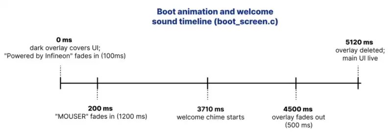
Display and touch interface
After the boot overlay fades, LVGL presents four tabs. **RADAR** plots signal data, while **CAMERA** fills the screen with the live feed. **BABY MON** combines a 400 × 300 camera view with cry-detection, motion-intensity, and audio panels. **SAFETY** shows a 480 × 360 camera view, breathing and crib-presence indicators, and **Play Lullaby**, **Mute**, and **Cam** controls. The privacy behavior is the more considered part of that screen. On the SAFETY tab, the camera stays hidden until the baby cries or breathing can’t be confirmed. It remains visible for ten seconds after the alert clears, and the Cam button can reveal it on demand.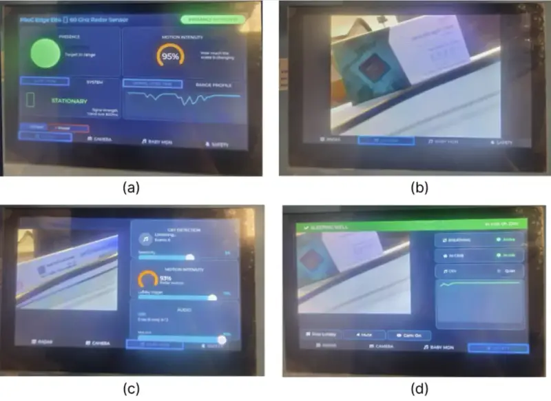
USB camera preview
The camera path is event-driven. Each USB video callback copies incoming packets into one of two YUYV accumulation buffers in SoCMEM. When a frame is complete, the camera task converts it to RGB565 with integer BT.601 arithmetic, taking about 2 ms, cleans the D-cache so the GPU sees current pixels, and hands the frame to the UI. If processing falls behind, the callback drops arriving frames instead of blocking the stream. Reconnection is handled while the system runs: after an unplug, the task waits for the USB device to return before resuming capture. On first boot, the serial messages `[Camera] USB camera streaming` and `[Cam] First USB frame!` indicate startup; nonzero bytes in that first frame confirm pixel data is arriving.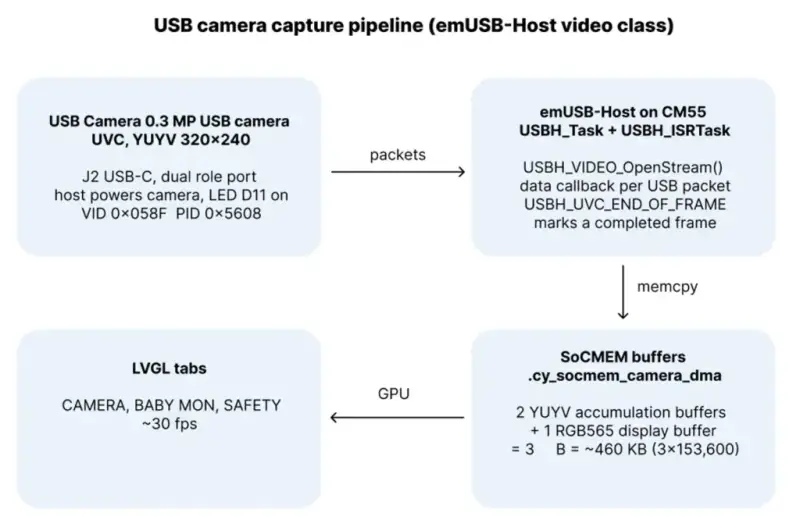
Debugging a DMA-related HardFault
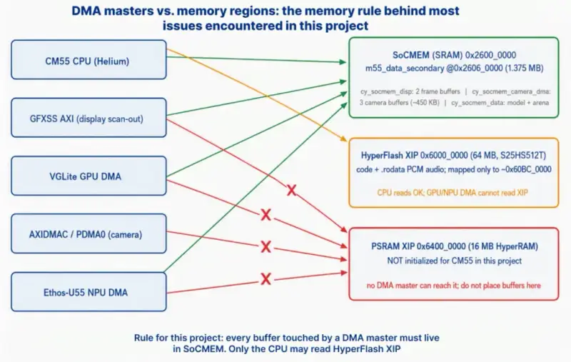
An imprecise fault with `CFSR = 0x00000400` during camera startup gives the CPU no precise failing access to report. The failure had two layers: a face-recognition experiment added `psram_init()`, which corrupted PSRAM access; after removing that call, a camera buffer still sat in a PSRAM linker section, so the first `memset()` hit an unmapped range. The fix was to put every camera buffer in SoCMEM and remove PSRAM use from CM55. The three QVGA buffers consume about 450 KB of the 1.375 MB SoCMEM region.Table 3. Buffer locations required for the DMA masters used in this project
| Buffer | Linker section | Region | Reason |
|---|---|---|---|
| LVGL frame buffers (×2) | .cy_socmem_disp (NOLOAD) | SoCMEM | Display scan-out cannot read PSRAM |
| USB YUYV accumulation buffers (×2) | .cy_socmem_camera_dma (NOLOAD) | SoCMEM | Filled per USB packet in USBH task context |
| Camera RGB565 display buffer | .cy_socmem_camera_dma (NOLOAD) | SoCMEM | CPU converts it; GPU draws it |
| babycry model and tensor arena | .cy_socmem_data | SoCMEM | NPU DMA cannot read PSRAM |
| PCM audio (song and chime) | Default .rodata | HyperFlash XIP | Read by the CPU inside the TDM interrupt |
| VGLite GPU heap | gfx_mem at 0x26200000 | SoCMEM | GPU-only region, 3 MB |
Speaker audio playback
Audio playback runs from the TDM interrupt. At 48,000 samples per second, the peripheral signals when its small FIFO runs low; the handler then supplies the next 32 to 64 samples from the PCM arrays in flash. It duplicates mono samples across the stereo slots and applies volume scaling. Since the CPU can read flash, these arrays don’t need a RAM copy; the SoCMEM restriction applies to DMA hardware.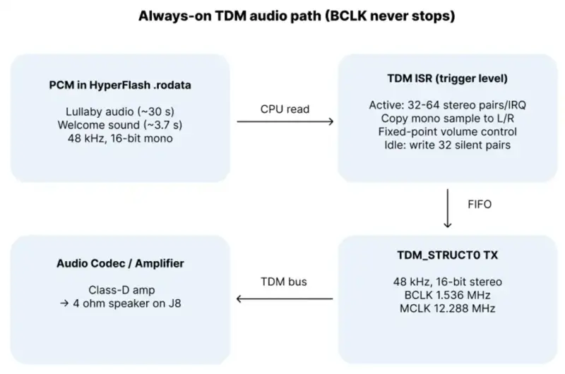
Making the Monitor Work Reliably
Several failures came down to clocks and state, not faulty peripherals. The buzzer’s TDM clock gate had never been opened, and transmission wasn’t enabled before activation. Because the registers remained readable, the missing clock produced little obvious evidence: writes simply had no effect. Initializing the peripheral clock with Cy_SysClk_PeriGroupSlaveInit(CY_MMIO_TDM0_PERI_NR, …), then calling Cy_AudioTDM_EnableTx(CYBSP_TDM_CONTROLLER_0_TX_HW) before Cy_AudioTDM_ActivateTx(CYBSP_TDM_CONTROLLER_0_TX_HW), fixed the startup sequence.
A separate clocking issue affected the display. Device Configurator had assigned the codec’s I²C bus and SCB5 to the same divider. The codec driver’s mtb_hal_i2c_configure() call changed that shared divider, disrupting I²C timing on the display bus. Removing the call restored operation because the generated configuration already held the right settings for both buses. If unrelated buses fail together, check whether they share a divider.
Playback had another trap: stopping TDM also stopped BCLK, the clock the codec uses to stay synchronized. After the first sound, the codec lost sync and stayed silent. The fix was to start TDM once in buzzer_init() and keep it running. While idle, the interrupt handler feeds zeros at a reported cost of about 0.03 percent CPU; play and stop requests change flags without touching the TDM hardware.

Separating Real Signals from Noise
The cry detector analyzes audio in half-second windows and sends each window to the DEEPCRAFT model running on the NPU. The model returns a crying confidence score, which the UI’s sensitivity setting—from 1 to 5—uses to set its threshold. Detections persist for two seconds to avoid flicker, then receive timestamps in a rolling list used by the song logic. Offloading inference to the NPU lets graphics and audio continue running.
Radar processing takes a different route. Each frame becomes a range-gated magnitude value used to estimate signal strength, motion, presence, and breathing. Presence turns on above 60 percent and clears below 45 percent, with hysteresis and debounce timers smoothing transitions. That gap matters: a single threshold can make a status indicator chatter when readings hover around the boundary.
Breathing detection looks for changing reflections in the approximate 0.1–1.5 Hz range associated with chest motion. The system subtracts a slow baseline from a faster low-pass-filtered signal to isolate that variation. A person in range should produce sustained movement in this band; a wall or piece of furniture should not. Presence also requires breathing or motion within the previous 15 seconds, so a strong but inactive reflection cannot keep the system reporting a target. During song playback, motion alerts are suppressed to prevent the speaker from triggering a fresh alert.
That distinction between signal strength and signal behavior also fixed a misleading “BREATHING: Active” reading when the radar was covered. The earlier indicator treated reflection strength alone as evidence of breathing, while presence used a single 55 percent threshold and flickered near that value. Replacing the strength check with band-pass life-sign detection, and restoring the 60/45 percent hysteresis thresholds, addressed both problems. Serial output appears every five seconds in this format:
[Radar] sig= mot= br= life= pres=
Compare br= with a person in range and with the sensor covered. If the readings don’t separate clearly, adjust BREATH_MIN_LVL until breathing activity can be distinguished from a blocked or inactive sensor.
Playback, Memory, and the Final Build
The song state machine combines the cry and motion signals. It starts looped playback after at least three cries within five minutes, or when motion reaches 70 percent and stays there for eight seconds. Playback stops after two calm minutes—no cries and motion below 20 percent—subject to a 60-second minimum run time. Buttons in the SAFETY tab use the same start and stop functions.
MP3 decoding exposed how easily a small task stack can be overwhelmed. The decoder state, about 6.5 KB, and output buffer, about 4.5 KB, were local variables on an 8 KB stack. Making them static and raising the task stack to 16 KB stopped the first HardFault. A second overflow came from a roughly 16 KB scratch structure declared locally inside minimp3.h at line 1718; changing it to static mp3dec_scratch_t resolved that fault. Decoding then worked, but it still demanded significant CPU time. Converting the audio to PCM on a PC with FFmpeg and storing it in flash proved simpler and more efficient.
Flash placement caused a different fault. A 2.88 MB song placed at 0x60C00000 triggered a BusFault on its first read, even though the task stack was valid. That address sits beyond the CPU’s XIP window, which ends near 0x60BC0000 at the CM55 partition; the selected flash existed but wasn’t mapped. Removing the custom section and linker flag returned the array to standard .rodata. With the partition expanded to 6 MB, the full 5.4 MB image fits in the mapped window.
The reported build now plays its boot chime, looped song, and UI sounds through unlimited play and stop cycles. Its four-tab interface shows a live 320×240 USB camera preview at about 30 fps, with YUYV converted to RGB565 on the CM55; unplugging and reconnecting the camera doesn’t require an application restart. Cry detection runs continuously on the NPU, radar motion updates every 100 ms, and presence and breathing indicators stay steady. The SAFETY camera appears during alerts or on demand, both song triggers have been verified, and auto-stop engages after two calm minutes.
Those results fit within roughly 5.4 MB of the 6 MB CM55 flash partition. SoCMEM use is reported as about 1.5 MB for frame buffers and 450 KB for camera buffers, plus the model and arena.
A Capable Prototype, with Clear Limits
The notable achievement is concurrency: one edge-AI microcontroller prototype runs GPU-accelerated graphics, continuous 48 kHz audio, radar analysis, USB video, and neural-network inference, with the NPU handling the model. Combining microphone, radar, and camera inputs can make monitoring more informative because each sensor helps cover the limitations of the others. All audio, video, and sensor processing stays local, providing real-time feedback without sending private data to the cloud.
That’s a strong prototype result, but it doesn’t by itself establish how the system performs as a finished monitor. The design still has room to grow: it has about 52 MB of available flash and an idle CM33 core. Possible additions include Bluetooth Low Energy or Wi-Fi alerts, event logging, configurable detection thresholds, sensor-fusion confidence scores, more audio or vision models, and lower-power modes. Whether those additions improve the system will depend on how well they preserve the qualities already demonstrated: local processing, responsive operation, and privacy.
 Choosing Single, Double, Welded Flap and Repair Keder for Fabrication
 Houston Engineering Team Builds a Welcoming Golf Tournament at East River 9
 MIG Transfer Modes: Choosing Between Short Circuit, Spray and Pulse