CNC Programming: From CAD Geometry to Accurate, Repeatable Machining
CNC programming turns part requirements into toolpaths and machine commands, shaping accuracy, surface finish, cycle time and production consistency.
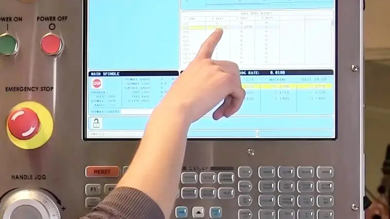
A CNC machine’s accuracy matters only when its instructions match the part and the manufacturing process. CNC programming supplies that link: it translates a digital design into tool movements, cutting conditions and an operation sequence that the machine can execute.
Those decisions affect more than whether a tool reaches the right coordinates. They influence dimensional accuracy, surface finish, tool life, cycle time and the chance of collisions. CNC programming is therefore a manufacturing engineering task as much as a coding task.
From design requirements to machine instructions
Programming starts with the part’s geometry and its manufacturing requirements. A 3D CAD model describes the shape, while a 2D drawing may specify dimensions, tolerances, surface roughness, material, threads and geometric requirements. Together, these define what the finished component must achieve.
The programmer uses that information to plan how to make the part. The plan covers the machine, tools, workpiece position, number of setups, operation sequence and cutting parameters. It also addresses how the required tolerances and surface finishes will be produced. A good toolpath has to fit the part, the available equipment and the intended production process.
The overall flow is CAD model → CAM programming → toolpaths → CNC program → machine operation → finished part. Errors or unsuitable choices at any stage can carry through to the final component.
CAM software and machine code
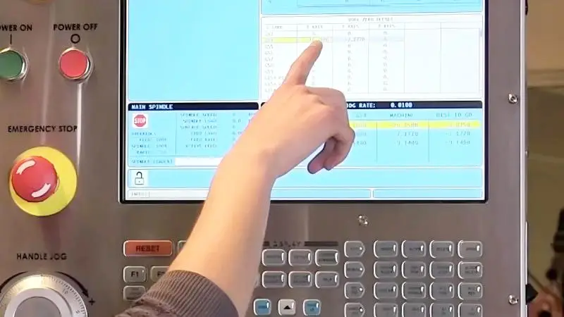
For simple work, a programmer may write some instructions by hand. Complex components are commonly programmed with Computer-Aided Manufacturing (CAM) software, which uses the CAD geometry and manufacturing plan to calculate toolpaths. The programmer selects a strategy and sets details such as tool geometry, cutting depth, step-over, feed rate, spindle speed and machining tolerance.
CAM software can simulate the planned toolpath before the program reaches the machine. That gives the team a chance to review the sequence and spot potential problems in advance. The software still depends on sound choices from the programmer: generated code can only carry out the strategy and parameters it was given.
Machine instructions are commonly expressed using G-code and M-code. G-code generally describes movements and geometric commands, including rapid positioning and linear or circular interpolation. M-code generally controls machine functions such as spindle operation, coolant, tool changes and program stops. Available commands and syntax vary by controller.
A CAM system usually converts toolpaths into machine code through a post-processor configured for the machine and its controller. That configuration matters because a program must use commands the intended equipment can interpret.
Tool movement and machining strategy
The program controls where the cutting tool travels. A typical three-axis machining center moves along X, Y and Z; four-axis and five-axis machines add rotary movement. A basic milling sequence might position the tool, move it into a feature, cut along a defined path, retract and continue to another operation. With five-axis machining, the tool can change orientation as the machine moves across several axes, making planning more demanding.
Programming also determines how material is removed. A part may be roughed to remove material, semi-finished and then finished to reach its final dimensions and surface quality. For complex pockets, an adaptive or high-efficiency roughing strategy may help maintain more consistent cutting conditions; finishing passes can then follow the required contours.
The shortest path or fastest material removal rate isn’t automatically the right choice. A strategy must balance productivity with tool life, dimensional accuracy, surface finish, machine capability and the part’s requirements. Those factors can lead to different toolpaths for the same component.
Cutting conditions, accuracy and finish
Spindle speed, feed rate, depth of cut and step-over are among the parameters a program specifies or incorporates. Suitable values depend on the workpiece material, tool material and geometry, tool diameter, machine rigidity and spindle capability, as well as the feature being machined and the required finish.
Inappropriate settings can increase cutting forces, deflect a tool or cause it to fail early. Excessive spindle speed can add heat and accelerate wear, while a feed rate that doesn’t suit the operation can hurt finish or efficiency. Choosing parameters calls for an understanding of both the software and the cutting process.
The toolpath defines where the tool travels, but it can’t guarantee the finished dimensions on its own. Tool geometry, machine accuracy, workholding, material behavior and cutting conditions all contribute. For precision work, the programmer may account for tool diameter, wear and machine characteristics. The machine, tooling, setup, inspection process and manufacturing environment must also support the required tolerance.
Surface texture depends on programming choices too. Toolpath direction, step-over, feed rate, spindle speed, cutting depth and tool geometry can leave different marks. For a contoured surface, a suitable finishing step-over can reduce visible scallops. A part may meet its dimensional requirements yet still show unwanted machining marks if the finish strategy is poorly chosen.
Complex parts and production planning
Five-axis machining shows why programming needs to account for the whole setup. Rotary motion can let a tool approach features from different directions, reducing setups and reaching geometry that may be difficult to access on a conventional three-axis machine. The programmer must plan tool orientation while accounting for collisions, machine limits, workpiece geometry, holder clearance and cutting conditions.
Production volume also shapes the programming approach. On a prototype or low-volume job, quick setup and easy adjustments may matter more than minimizing every second of cycle time. For a larger run, it may make sense to spend more effort refining toolpaths, extending tool life and automating repeated operations. Even a small cycle-time reduction can add up across many components.
Once a program has been validated, it can support repeatable production. Combined with tool changers, probing, robotic loading and unloading, pallet systems and in-process measurement, CNC programming can form part of an automated manufacturing process. Consistent output still depends on maintaining the conditions the program expects.
The programmer’s role in a CAM-driven shop
CAM software automates much of the code generation, but it doesn’t remove the need for machining knowledge. The programmer must judge whether a toolpath suits the machine, material, tooling and part requirements, then review its behavior before production. That work increasingly involves process planning, tool selection, simulation, optimization and troubleshooting.
Programmers may work with design, manufacturing, machining and quality teams to connect the drawing’s requirements with production and inspection. Feedback from measured parts and shop-floor results can reveal where a sequence or parameter needs refinement.
Programming as a continuing process
Reliable programming begins with a careful drawing review, identification of critical dimensions, and a workable sequence that accounts for tool access and workholding. Simulation and review help check the planned paths; production experience and inspection results can then inform adjustments.
That cycle—design, programming, machining, inspection and process improvement—is what turns a program that runs into a manufacturing process that repeatedly produces parts to specification. The machine provides the motion and cutting capability. The program determines how that capability is applied to the component.
 Choosing Single, Double, Welded Flap and Repair Keder for Fabrication
 Houston Engineering Team Builds a Welcoming Golf Tournament at East River 9
 MIG Transfer Modes: Choosing Between Short Circuit, Spray and Pulse