CNC Machining Brass: Factors That Control Accuracy, Finish and Part Quality
Brass machines efficiently, but alloy choice, tooling, workholding and finishing determine whether parts meet dimensional and surface requirements.
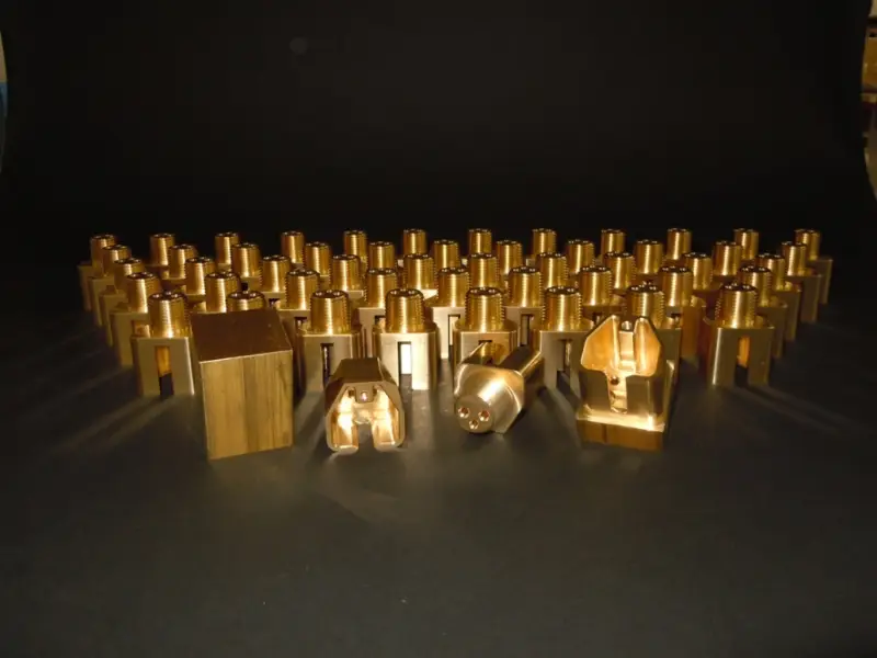
Brass is straightforward to machine compared with many harder engineering metals, but that doesn’t make precision automatic. Alloy selection, tool condition, clamping, cutting parameters and machining sequence all affect whether a part holds its dimensions and achieves the required finish. Those choices matter across electrical hardware, automation equipment, plumbing and precision instruments.
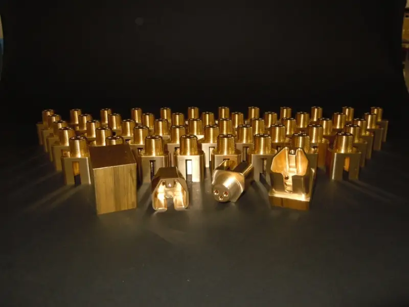
Why brass suits precision machining
Many brass alloys machine well in turning, milling, drilling and tapping. Their relatively manageable cutting forces support efficient production, and the material can accommodate small holes, threads, slots and grooves. With suitable material and process choices, manufacturers can also produce repeatable dimensions across a production run.
Brass brings other useful properties: corrosion resistance, electrical conductivity and an appearance that may suit exposed components. The balance varies by alloy. Leaded free-cutting brass is known for easy machining, while other grades may be chosen for strength, corrosion resistance or electrical performance. The part’s actual mechanical and environmental requirements should guide the specification.
What controls dimensional accuracy
Machine positioning is only one part of the accuracy picture. Spindle runout, axis errors, worn guideways and poor calibration can all affect dimensions. Tool condition matters too: a worn cutting edge can raise cutting forces and heat, contributing to dimensional variation and a poorer finish. Runout deserves particular attention on small holes and other precision features, where it can produce oversized or uneven cuts.
Cutting speed, feed rate and depth of cut need to match the alloy, tool geometry, feature size and operation. Brass can generally tolerate relatively high cutting speeds, but raising speed alone doesn’t guarantee faster or cleaner production. Excessive speed can increase heat and tool wear; an unsuitable feed can leave visible marks or make dimensions harder to control. Parameters should be tuned for the part rather than chosen only from general-purpose recommendations.
Workholding is another source of variation. Thin walls, narrow sections and delicate features can distort under excessive clamping force or cutting pressure. A fixture should support the part consistently while holding it in position. For slender or complex components, the clamping approach can have as much influence on the result as the selected cutting parameters.
Machining order also affects stability. Roughing removes material and may release internal stresses, so tight-tolerance parts can benefit from separate roughing, semi-finishing and finishing operations. Critical dimensions can be cut after bulk material removal, when the part has settled into a more stable condition.
Getting the required surface finish
A clean machined surface depends on sharp tools, suitable geometry, stable workholding and a controlled feed. Finishing passes can reduce visible tool marks on flat faces and cylindrical features. Chip evacuation matters as well: chips that collect in the cutting area can scratch the part or be cut again, disrupting the finish.
When surface texture is a functional requirement, the engineering drawing should specify the target Ra value. That gives the manufacturer a defined finish to work toward and informs the machining and any secondary finishing steps.
Some parts need more than the finish produced by machining. Polishing can improve smoothness and appearance on decorative or exposed components. Brushing, plating, coatings and other treatments may be selected to meet appearance or functional requirements. The chosen process should be considered alongside the alloy and dimensions: a treatment can add material to a surface or remove some, affecting tight tolerances. Planning for the final treatment during machining helps preserve critical dimensions.
Choosing the machining process
CNC turning suits cylindrical brass parts such as bushings, spacers, shafts, fittings, connectors and threaded components. It can support productive manufacturing while maintaining consistent dimensions.
Milling handles flat faces, pockets, slots, holes, contours and more complex shapes. Three-axis, four-axis or five-axis equipment can be selected according to feature access and part geometry. Drilling and tapping create mounting and threaded connection features; correct tooling and chip removal are especially important for small or deep holes.
For small-diameter parts with several precision features, Swiss-type machining can provide an efficient route with high repeatability. The process choice ultimately depends on the part’s geometry and the access needed to produce its features.
Where machined brass parts are used
Electrical and electronic assemblies use brass for terminals, connectors, contact parts and threaded inserts. Its conductivity and machinability suit components that need accurate dimensions and dependable electrical connections.
Automation equipment uses parts such as bushings, spacers, fittings, shafts, couplings and mounting components. Brass can fit applications that need machinability and corrosion resistance alongside dimensional control.
Valves, adapters, fittings and connectors are common in plumbing and fluid systems. Brass’s corrosion resistance and suitability for accurately machined threads make it useful in many fluid-handling applications. Selected automotive and transportation parts also use brass, including connectors, bushings, fittings and precision mechanical components. The appropriate grade depends on the required mechanical, thermal, electrical and environmental performance.
Instruments and precision equipment often contain small brass components where dimensional stability, appearance and repeatability matter. CNC machining allows manufacturers to produce complex features and maintain consistent dimensions between batches.
Process control and inspection
Reliable results start with a brass grade that meets the component’s requirements for strength, conductivity, corrosion resistance and machinability. The process plan should then reflect the geometry and tolerances, including separate roughing and finishing steps where needed. Tool wear should be monitored during production because a tool that cuts accurately at the start of a run may gradually shift dimensions as it wears.
Inspection methods should match the required tolerance and feature. Calipers, micrometers, gauges and height gauges can verify dimensions; optical systems and coordinate measuring machines (CMM) can check more complex features. First-article and in-process inspection can catch deviations before they affect a larger batch.
Drawings should identify the dimensions that directly control assembly, movement, sealing or electrical connection. Giving every feature an unnecessarily tight tolerance can add machining time and cost without improving how the part works. Focusing tighter limits on functional dimensions helps align inspection effort and process control with the component’s job, particularly in custom or low-volume production.
Brass offers a useful mix of machinability, conductivity and corrosion resistance, but the alloy alone doesn’t determine part quality. A process built around the functional dimensions, surface requirements and final treatment is what turns that material advantage into repeatable components.
 Choosing Single, Double, Welded Flap and Repair Keder for Fabrication
 Houston Engineering Team Builds a Welcoming Golf Tournament at East River 9
 MIG Transfer Modes: Choosing Between Short Circuit, Spray and Pulse